
Up close and personal
This here is called the 'front'. I'll do my best to avoid technical jargon, but bear with me. You can see some hidden lines in this picture, those are showing the layout of each of the parts. Also, it is worth noting that the screen size shown here is slightly smaller than actual--I forgot how thick I was supposed to make the border, so just stuck it in as-is. Next, from the rear:


So, for identification purposes, the three light gray blocks are batteries, and were probably the hardest to place. The large green square above them is the charge/discharge circuit, and just outside of the frame I actually have a couple of Anderson Powerpoles which were to be the power plug. The largest green circuit board in the upper right would be the motherboard from the GameCube, situated directly right of the memory card slot (off-white), SD card slot (orange, upper), and the WASP (orange, lower). Immediately below, one may observe the audio amplifier, who's controls lay on the opposite end of the device. The green one is a volume knob, and the black one is a pair of headphone jacks. Between them is a small, slim green board which holds the buttons used to control the LCD controller board, which may be my favorite: it's not easy to see from this angle, but it's actually tilted down. There was no way to fit it in flat with all the other components taking so much room, so it juts out, giving Abe here a Gameboy Color-esque ass. In the end I found out that a 1 inch thick portable is insanely slim, given the usual thickness of GCN portables. Altogether, I think I'm happy with it thus far, I just need to 3D print that case. Speaking of which...
*Dun-Dun-Dun*
Here's a quick rundown of the major points:
-controlled only by an Arduino. No shields, no add-ons of any kind, only basic circuitry (switches, transistors, etc.)
-must use only a normal, DC motor, the kind you could pull out of any old appliance. No steppers.
-$100 budget, at the most. Ideally we should aim lower.
-Any parts that need to be custom made, like the frame, should be able to be cut from any chunk of wood with basic tools. This means no laser cutting, no plasma cutting, just what can be done with a circular saw, jigsaw, a drill, and some sand paper.
What you should say to yourself is, "how can I build this without paying for anything?" After the fact, what I expect to happen is one will make their own basic framework, then 3D-print better parts to gradually increase the precision of the machine. So far, my minimal-budget mechanism ideas are as follows:
Stepper Motor Alternative
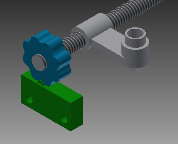
so I was thinking about how I could just make a really nice, small step motor with nothing but a DC motor and a switch, and something something got this idea. The green part is a VEX lemit switch, and the blue part is one you'd have to make yourself. Now I know what you're thinking: "how the flagship am I supposed to make something that small and precise?!" Weeellllll, it just so happens that when I made the part, I discovered that you can put in all the necessary constraints, but still make it as big as you like. Just pick a radius, print a profile, staple to your plywood and you're in business.
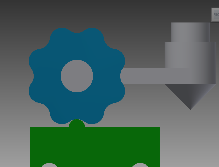
Plate Rests
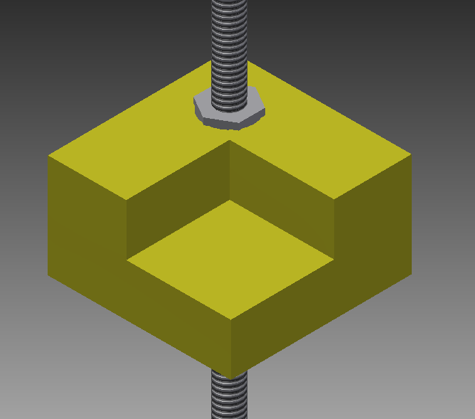
This one's a little more intimidating, but I assure you it can be done. I imagine one would first cut the top and bottom out of 1/2" plywood, then glue them together. The hole can just be an interference fit for a 7/16 nut, plus you could fill the edges with hot glue or something. (not in the tool list, I know, but still common enough.) Both of these design use 1/4" allthread, and you can get more than enough of that on Mcmaster-Carr. (6ft for $4) This does mean that leveling your plate would mean individually spinning each corner around and around until it's just so. Also I realize there are a few parts that I left open-ended here, like how to attach an encoder wheel to allthread, but I think you're all clever enough for that. So by my calculations, if one uses 1/4-20 allthread and the 8-lump encoder wheel shown here, you can get a precision of 1/320th of an inch, or just under 80 microns. For comparison, a MakerBot Replicator2 goes down to 20 microns--a tolerance that we can beat with a simple 3/13 gear train, printed from the initial machine. Obviously there are plenty of other ways to do it, but that's the one that came to mind first.
I have found myself to have bitten off a bit more than I can chew trying to convert stl files to a step-code that this design could use, so I'm thinking of using Slic3r or one of the many existing slicing engines out there, then working from their .gcode. That'll be my next contribution, though it may not come for quite a while. Until then, I'm sure everyone can keep busy with this little springboard here. Good luck.
K
No comments:
Post a Comment